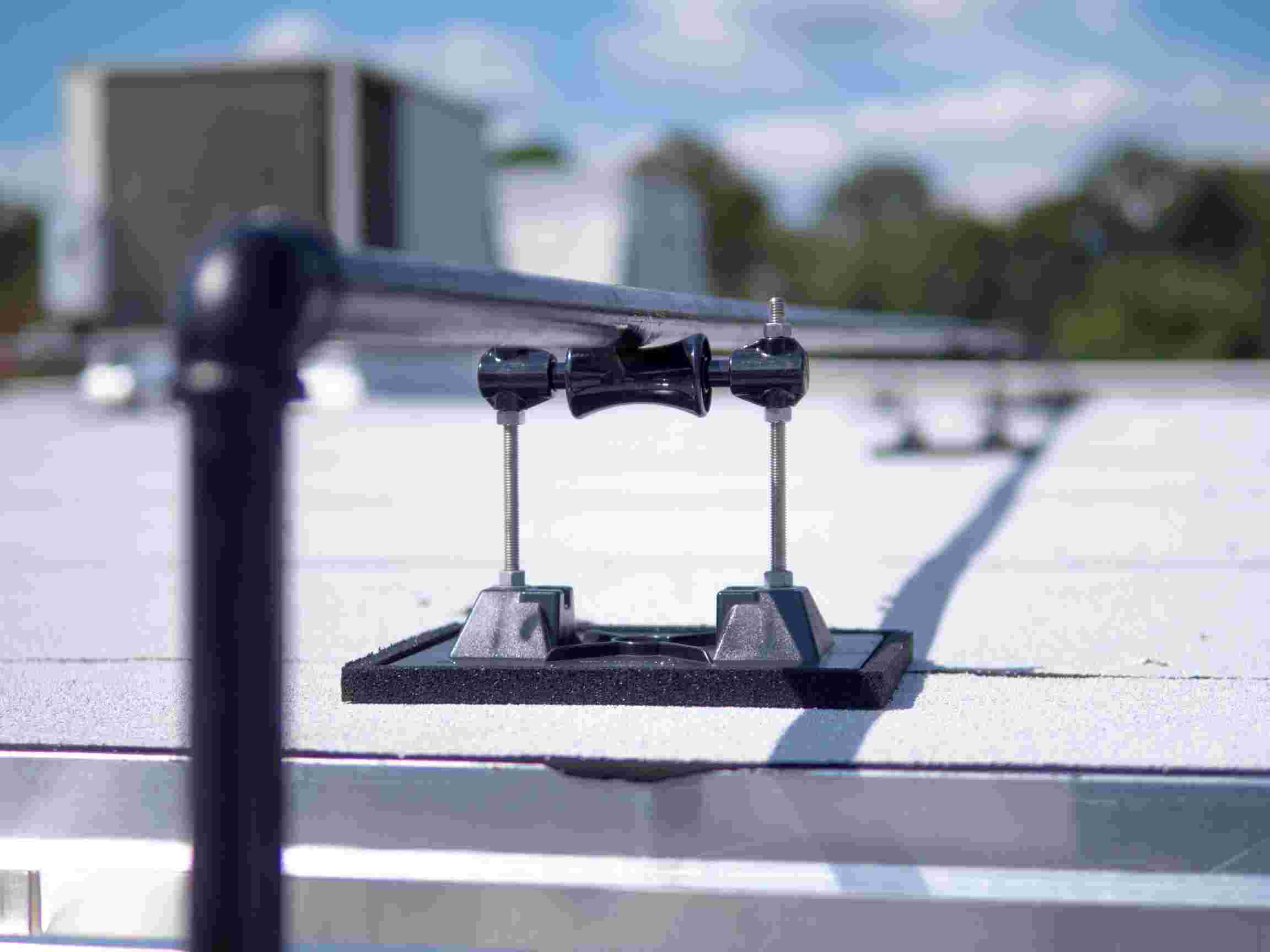
A pipe roller support is a type of roof pipe support that cradles a pipe on a self-lubricating roller, allowing the pipe to slide longitudinally as it expands and contracts with temperature changes — all without penetrating or damaging the roof membrane. When a piping system experiences thermal movement, and the supports cannot accommodate it, stress accumulates at fixed contact points, eventually causing damage to fittings, anchors, and the roof membrane itself.
Not every pipe run requires rollers, and specifying the wrong support type wastes budget. This guide explains when roller pipe supports are the right choice, how rooftop support blocks work, how to read MIRO Industries’ sizing data, and the most common specification mistakes to avoid.
What Is a Pipe Roller Support?
A roller pipe support is a non-penetrating rooftop support designed specifically for expansion and contraction applications. According to MIRO Industries’ Roller Series product page, the roller is made from self-lubricating polycarbonate resin, which allows the pipe to move freely along its axis. All metal parts in MIRO Industries roller supports are stainless steel, and the base is UV-stable polycarbonate — engineered to resist the cracking and crumbling that affects rubber, foam, and polypropylene alternatives under prolonged UV and weather exposure.
The roller cradle rests on top of the base, which is the only component in contact with the roof membrane. By distributing the pipe load across a wider footprint and eliminating the need for fasteners that penetrate the membrane, the base preserves the roof’s waterproofing integrity—an essential requirement for any commercial flat roof.
Roller vs. Fixed Support: When Does Thermal Movement Require a Roller?
Thermal expansion is the core reason roller pipe supports exist. Carbon steel pipe expands approximately 0.75 inches per 100 feet for every 100°F of temperature rise, based on published thermal expansion coefficients referenced in ASME B31.3 Table C-6. For a 100-foot steam line rising from 70°F to 350°F, that means roughly 2.1–2.3 inches of movement that must go somewhere.
Source: ASME B31.3 Table C-6 (Coefficients of Thermal Expansion for Piping Materials). Engineering Toolbox and multiple piping engineering references publish consistent values of ~6.3–6.7 × 10⁻⁶ in/in/°F for carbon steel.
If the supports are fixed and cannot accommodate that movement, the pipe pushes against its restraints. The resulting axial force on a restrained 4-inch Schedule 40 carbon steel pipe under a 200°F temperature rise can exceed 50,000 pounds, according to piping flexibility references based on ASME B31.3 allowable stress calculations. That force has to go somewhere — and it typically goes into cracked welds, lifted anchors, and damaged roof membranes.
Use a roller pipe support when any of the following apply:
- The pipe carries steam, hot water, refrigerant, or any fluid with a significant temperature variance from ambient
- The system will experience frequent thermal cycling (e.g., seasonal HVAC changeovers, boiler startups)
- The pipe run is long enough that calculated thermal expansion will create meaningful longitudinal movement — use ASME B31.1 Table 121.5 or consult your mechanical engineer to determine the threshold for your specific pipe material, size, and temperature delta
- The project is in a climate with significant seasonal temperature swings, amplifying ambient expansion and contraction
A fixed support — such as a pillow block support — may be appropriate when:
- The pipe run is short and carries ambient-temperature or cold fluids with minimal thermal delta
- The system is an electrical conduit, cable tray, or another non-thermally active run
- A fixed anchor point is required at the end of a roller-supported run — every roller system still needs at least one fixed anchor to prevent the pipe from walking in one direction over time
The table below summarizes the recommended support type by application:
| Application | Roller Pipe Support | Fixed (Pillow Block) Support |
| Thermally active pipes (steam, hot water, refrigerant) | ✔ Recommended | Not suitable — pipe cannot expand freely |
| Long straight runs (see ASME B31.1 spacing guidance) | ✔ Recommended | Risk of stress buildup at fixed points |
| Frequent thermal cycling (e.g., seasonal HVAC changeovers) | ✔ Recommended | May cause fatigue at anchor points |
| Short runs, ambient-temperature service | Optional | ✔ Typically sufficient |
| Electrical conduit or cable tray | Optional | ✔ Common choice |
| Fixed anchor point at end of roller run | Not used here | ✔ Required — at least one per run |
For a broader look at how support type selection fits into the overall design process, see Best Practices for Securing Pipes on Commercial Rooftops.
What Are Rooftop Support Blocks, and How Do They Work with Rollers?
“Rooftop support blocks” refers to the base assembly that sits directly on the roof membrane and elevates the pipe cradle above the surface. The base block is the component that contacts the roof — the roller cradle is mounted on top of it. In a roller pipe support system, the base block serves three functions:
Membrane protection: The block spreads the pipe load over a wider footprint rather than concentrating it at a single contact point. MIRO Industries’ base footprint dimensions vary by model — larger and heavier pipe applications use wider bases to distribute load at lower pounds-per-square-inch against the membrane. Refer to the individual product specification pages for the base dimensions of each model.
Height elevation: The block raises the pipe clear of the roof surface to allow for insulation thickness, proper drainage, and maintenance access. The height range available across MIRO Industries’ Roller Series spans from approximately 3.6″ minimum to 18″ maximum, depending on the model selected. See the Sizing section below for per-model height ranges.
Non-penetrating installation: A properly designed rooftop support block requires no fasteners through the roof surface, preserving the membrane and — importantly — the membrane manufacturer’s warranty. According to MIRO Industries’ published product description, the design “allows the pipe support to achieve stability without penetrating or damaging the roof membrane.”
Source: MIRO Industries Roller Series product page — miroind.com/product-category/roller-supports/. Per-model base dimensions and height ranges are listed on each product page within that category.
Material is where commodity products often fall short. Rubber and foam bases are common in lower-cost supports, but they deteriorate under UV exposure and freeze-thaw cycling. MIRO Industries’ polycarbonate bases are UV-stabilized for the full lifetime of the roof — which is why they’re backed by a 20-year warranty.
For conduit and cable tray applications where a fixed cradle is preferred over a roller, MIRO Industries strut supports use the same durable base system with a rigid strut cradle instead.
Roller Pipe Support Sizing: What the Product Specs Actually Say
The table below is compiled from published MIRO Industries product specifications. Always verify the current specs on the individual product pages, as models are updated periodically.
| Model | Max Pipe OD | Height Range | Max Load / Stand | Max Spacing* |
| 2-RAH-5 | 2.5″ | 3.625″ – 5″ | 140 lbs | ≤ 10 ft |
| 3-RAH-8 | 5.5″ | 3.875″ – 8″ | 172 lbs | ≤ 10 ft |
| 3-RAH-12 | 5.5″ | 3.875″ – 12″ | 172 lbs | ≤ 10 ft |
| 4-RAH-10 | 5.5″ | 4.5″ – 9.5″ | 335 lbs | ≤ 10 ft |
| 4-RAH-14 | 5.5″ | 4.5″ – 13.625″ | 186 lbs | ≤ 10 ft |
| 5-RAH-8 | 8.5″ | 4″ – 8″ | 335 lbs | ≤ 10 ft |
| 5-RAH-12 | 8.5″ | 4″ – 12″ | 335 lbs | ≤ 10 ft |
| 6-RAH-8 | 8.5″ | 4.375″ – 8″ | 578 lbs | ≤ 10 ft |
| 6-RAH-12 | 8.5″ | 4.375″ – 12″ | 578 lbs | ≤ 10 ft |
| 10-RAH-8 | 13″ | 6″ – 8″ | 960 lbs | ≤ 10 ft |
| 10-RAH-18 | 13″ | 6″ – 18″ | 803 lbs | ≤ 8 ft |
* Manufacturer’s recommended spacing is not to exceed the listed centers, depending upon the load, per each model’s published specification sheet.
All specs verified from individual MIRO Industries product pages. Models covered: 2-RAH-5, 3-RAH-8, 3-RAH-12, 4-RAH-10, 4-RAH-14, 5-RAH-8, 5-RAH-12, 6-RAH-8, 6-RAH-12, 10-RAH-8, 10-RAH-18. Full product listings at miroind.com/product-category/roller-supports/.
What About Code-Based Spacing Requirements?
MIRO Industries’ published spacing figures represent the manufacturer’s structural limit per support. Code-required spacing is a separate determination governed by the applicable piping code for the project.
ASME B31.1 (Power Piping) Table 121.5 provides the industry’s standard span table for steel pipe. The well-known rule of thumb derived from this table is: maximum support spacing in feet ≈ nominal pipe size in inches + 10. So a 4-inch steel pipe would have a maximum span of approximately 14 feet; a 6-inch pipe approximately 16 feet. This applies to horizontal runs of standard-weight carbon steel pipe at operating temperatures up to 750°F, without concentrated loads between supports (such as flanges or valves). ASME B31.3 (Process Piping) does not publish a span table — engineers calculate spacing individually for process applications.
Source: ASME B31.1 Power Piping, Table 121.5. Rule-of-thumb summary referenced in EnggCyclopedia (enggcyclopedia.com) and wermac.org, both citing ASME B31.1. Always use the current edition of the applicable code and consult the project’s mechanical engineer of record for final spacing determination.
The governing spacing for any given project is the more restrictive of the manufacturer’s limit (from the product spec sheet) and the code-required maximum span. Always consult your mechanical engineer of record for code-compliant spacing on your specific project.
5 Common Mistakes When Specifying Roller Pipe Supports
1. Specifying a fixed support on a thermally active run
When a pipe carrying hot water, steam, or refrigerant is fixed rigidly at every support point, thermal expansion has nowhere to go. The resulting longitudinal force is transferred into fittings, flanges, and anchors — and can lift supports off the roof membrane. Roller supports allow the pipe to move freely while keeping the load distributed across the membrane.
2. Measuring bare pipe OD instead of insulated OD
Support height and cradle width must account for insulation thickness. The 2-RAH-5, for example, has a maximum pipe OD of 2.5″ — meaning a 2″ bare pipe with 1/4″ insulation is at the model’s limit. Always measure your insulated OD when selecting the support model.
3. Choosing a rubber or foam base block
Rubber and polypropylene base materials dry out and crack under prolonged UV and freeze-thaw exposure. Once the base degrades, load redistributes to the membrane, and the support becomes unstable. UV-stable polycarbonate — as used in MIRO Industries supports — is the correct material for long-term exposed rooftop installations.
4. Forgetting the fixed anchor point
A roller support system still needs at least one fixed anchor per run to prevent the pipe from migrating in one direction over years of thermal cycling. Plan anchor locations during design, not as a field correction after installation.
5. Undercounting supports on a take-off
Support quantities are easy to miss on complex rooftop plans, especially where runs change direction or elevation. MIRO Industries offers take-off services to help contractors and specifiers get accurate counts from construction documents before ordering.For a deeper look at common installation errors, see Costly Mistakes to Avoid When Installing Rooftop Pipe Supports.
Get the Right Roller Pipe Support for Your Project
MIRO Industries manufactures a complete line of roller pipe supports, pillow block supports, strut supports, and custom hanger supports — all backed by a 20-year warranty and made in the U.S.A.
Ready to specify? Browse the full pipe support product line, use our Specifier Tools, or request a free quote.
Related Reading:
- Best Practices for Securing Pipes on Commercial Rooftops
- Costly Mistakes to Avoid When Installing Rooftop Pipe Supports
- MIRO Industries Take-Off Services Process
- The Electrical Contractor’s Guide to Non-Penetrating Roof Conduit Supports
- How to Choose the Right Rooftop Mechanical Unit Support