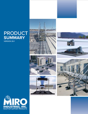
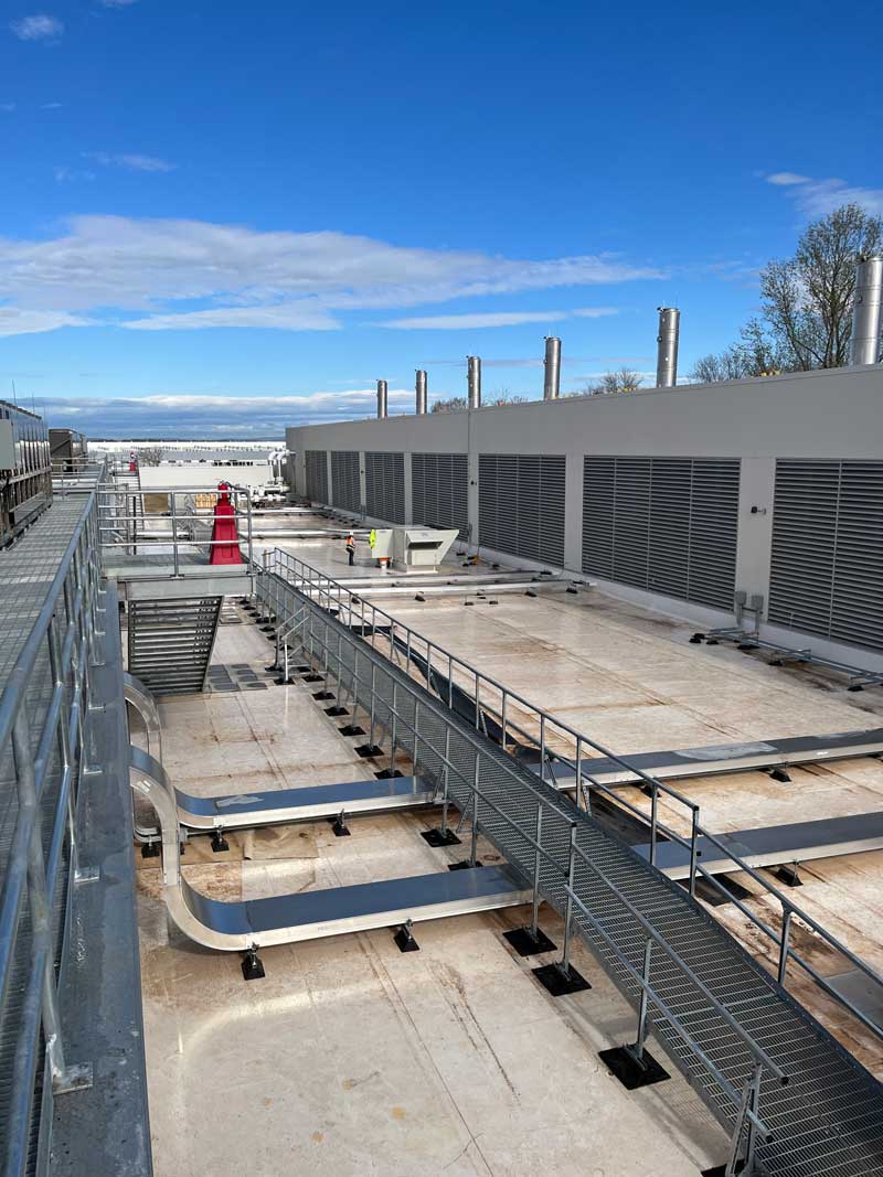
| Data center rooftop support systems involve higher pipe and cable tray density, more demanding wind and seismic requirements, tighter installation schedules, and very low tolerance for roof membrane damage or leakage compared to standard commercial HVAC projects. MIRO Industries designs and manufactures non-penetrating rooftop support systems that are commonly used in data center construction, including pipe supports, cable tray supports, mechanical unit supports, and access walkways. These systems can be coordinated from a single source. |
Data center construction has accelerated rapidly, and the rooftop of a data center is one of its most complex mechanical zones. Chillers, cooling towers, air handlers, condensers, refrigerant piping, power conduit, and fiber cable tray all compete for space on a roof that cannot afford a single leak. The rooftop support systems that work fine for a standard commercial building often fall short here, not because the products are wrong, but because the design assumptions are different.
This post covers what makes data center rooftop support different, what systems are typically required, and how to plan the layout to avoid the most common coordination failures.
What Makes Data Center Rooftop Support Different?
Higher system density
A standard commercial rooftop might have a few gas lines, refrigerant runs, and conduit. A data center rooftop can have dozens of high-voltage power feeders in cable tray, fiber runs, refrigerant piping to multiple cooling units, glycol or water loops for liquid cooling systems, and supply and return ductwork, all running across the same roof at the same time.
The support system has to accommodate this density without creating conflicts between systems, blocking access routes, or concentrating load at points the membrane and insulation weren’t designed to handle. This requires more planning at the layout stage than a typical commercial project, and it typically requires coordinating pipe supports, cable tray supports, and mechanical unit supports as a unified system rather than specifying them separately.
Membrane failure is not recoverable
A roof leak in a commercial office building is disruptive. A roof leak in an active data center can be catastrophic, directly threatening live equipment, triggering unplanned shutdowns, and creating liability that extends far beyond the cost of the repair. This makes membrane protection a first-order design requirement for every support installed on a data center roof, not a secondary consideration.
Non-penetrating supports that distribute load across wide base footprints and rest on the membrane without fastening through it are commonly preferred for data center rooftop systems because they avoid support-related fastener penetrations, reducing one potential source of membrane damage and warranty complications when properly designed and installed. When roof penetrations are proposed, warranty and leak risk are important considerations for data center owners. Starting with a non-penetrating system can simplify those considerations by avoiding support-related roof penetrations.
Risk Category, seismic, and wind requirements
Under the adopted building code (typically the IBC), data center facilities may be assigned Risk Category III or IV depending on their function, occupancy, the consequences of failure, and the requirements of the applicable jurisdiction. ASCE 7-22 uses the building’s Risk Category, along with site- and project-specific parameters, to establish applicable seismic and wind design criteria. For nonstructural components, the component importance factor (Ip) under ASCE 7-22 Chapter 13 is determined based on the component’s function and the specific conditions identified in Section 13.1.3; it is not automatically determined by the building’s Risk Category. Ip = 1.5 applies to certain components, while other components may use Ip = 1.0. The applicable Risk Category, Seismic Design Category, component importance factor, and other project-specific criteria should be confirmed by the project’s structural engineer and authority having jurisdiction.
In practice, depending on the assigned Risk Category, component importance, site hazards, rooftop location, wind conditions, and project-specific criteria, seismic and wind design requirements for rooftop pipe supports at a data center may be more demanding than those for a typical commercial project in the same location. MIRO Industries’ wind and seismic support systems are engineered for project-specific requirements, with calculations and documentation, including P.E.-stamped drawings when required. See how to meet ASCE 7-22 requirements for rooftop mechanical systems for a full breakdown of the compliance framework.
Schedule compression
Data center construction runs on timelines where days matter. Trades are sequenced tightly, commissioning milestones are contractual, and delays in one system propagate across the schedule. Rooftop support systems that require coring, flashing, and cure time or that require custom fabrication on the roof add days to critical-path activities.
Non-penetrating, prefabricated support systems eliminate the roof-coring step and can significantly reduce field welding, cutting, and custom fabrication compared to site-built penetrating systems, shaving days off critical-path installation schedules. For a project where the rooftop mechanical installation is on the critical path, the difference between a penetrating and non-penetrating support system can represent meaningful schedule recovery.
Systems That Require Support on a Data Center Rooftop
Cooling pipe and refrigerant runs
Data centers use substantial quantities of refrigerant, glycol, chilled water, and condenser water piping running between rooftop equipment and the mechanical systems serving the IT load. These runs are often long, carry significant weight when fully charged, and include combinations of large-diameter pipe and smaller-diameter branch runs, each requiring appropriate support spacing, roller supports for thermal expansion on long runs, and coordination with cable tray and conduit in shared corridors.
MIRO Industries’ rooftop pipe supports cover a range of pipe sizes and configurations for data center cooling system applications. Where thermal expansion is significant on long runs, roller supports, guides, expansion loops, or other movement provisions may be required depending on the piping system design.
Cable tray for power and fiber
High-density data centers route substantial amounts of power cable and fiber between utility service equipment, generators, and rooftop electrical and communications equipment. Cable tray is commonly used for these runs, and rooftop cable tray requires a properly designed support system to keep the tray elevated above the roof membrane, accommodate cable loads, and coordinate with other rooftop systems. Where power and optical-fiber cables are installed in the same cable tray or routing system, the installation must comply with applicable NEC requirements, including Article 770, Section 770.133, which establishes when optical-fiber cables may share a tray or raceway with electrical conductors and when separation or a listed divider is required. The support system should also coordinate tray elevation and routing with adjacent pipe and conduit systems within the same roof zone.
MIRO Industries’ cable tray supports use the same non-penetrating base system as the pipe supports, allowing cable tray and pipe runs to share a coordinated support layout without creating conflicts at crossing points. For a full overview of how cable tray supports work with other rooftop systems, see the rooftop cable tray support guide.
Power conduit
In addition to cable tray, data center rooftop electrical systems typically include rigid metal conduit for service entrances, generator connections, and equipment feeders. NEC spacing and clearance requirements apply to these runs the same way they apply to any rooftop electrical conduit, with the added complexity that data center conduit runs are often larger diameter, carry higher voltage, and require specific separation from communication systems. See the NEC conduit support guide for spacing and clearance requirements by conduit type.
Rooftop mechanical equipment
Data center rooftops carry significant mechanical equipment: air-cooled chillers, cooling tower cells, dry coolers, air handling units, and condensing units. Each requires a mechanical unit support that carries the equipment weight, keeps it elevated above the roof surface, and maintains the manufacturer’s required clearances for airflow and maintenance access.
MIRO Industries’ mechanical unit support systems cover a range of rooftop equipment applications from smaller condensing units to larger mechanical installations. Large chillers and cooling towers may require project-specific structural and load review to confirm the appropriate support configuration. For data center projects in wind or seismic zones, these supports can be engineered for the project’s applicable lateral load requirements.
Maintenance walkways
A data center rooftop with multiple chillers, cooling towers, and dozens of pipe and conduit runs is a complex environment that maintenance personnel need to navigate safely. Rooftop walkways that provide defined access routes, protect the membrane from foot traffic, and connect equipment service areas reduce membrane wear and create a safer working environment for ongoing maintenance.
MIRO Industries’ rooftop walkways integrate with the pipe support and cable tray support layout, allowing the access system to be coordinated with the mechanical systems from the start of the project.
Planning the Layout: Where Data Center Rooftop Projects Get Complicated
The most common coordination failure on data center rooftop projects is sequencing the support layout after the equipment layout is locked. When pipe runs, cable tray, conduit, and mechanical equipment are placed without a coordinated support plan, conflicts emerge in the field: supports that block access routes, cable tray and pipe runs that cross without adequate clearance, mechanical units that need to be shifted because the support bases conflict with drain locations.
Planning the rooftop support layout in parallel with the mechanical and electrical layout, rather than afterward, prevents these conflicts. The key coordination points:
Height coordination. Pipe runs, cable tray, and conduit that share a corridor need heights coordinated so they can cross or stack without conflicting. The support system needs to accommodate the required clearances between systems, including the NEC separation requirements between power cable tray and fiber.
Load distribution. High-density areas where multiple systems converge near major equipment connections, at cable tray risers, and at pipe manifold points can create concentrated loads that need to be distributed across more membrane contact area. Wider base configurations address this.
Access routing. Maintenance walkways need to be planned alongside the mechanical systems, not routed around them after the fact. A walkway that requires stepping over a pipe run because the support system wasn’t coordinated adds risk and reduces the usefulness of the walkway.
Wind and seismic bracing. On projects with significant wind or seismic demands, including many Risk Category III or IV data centers, the bracing and restraint layout should be part of the initial design, not added after the pipe runs are placed. Support bases that will need to be structurally attached to the building need to be identified early so the structural penetrations can be planned and detailed.
MIRO Industries works directly with MEP engineers and general contractors on data center rooftop layout, providing coordinated support designs that cover pipe, cable tray, conduit, mechanical equipment, and access systems from a single source. Contact your MIRO Industries rep or request a quote with the rooftop plan and system layout.
Frequently Asked Questions
Ip) under ASCE 7-22 Chapter 13 is determined based on the component and the specific conditions identified in the standard; certain components may require Ip = 1.5, while others may use Ip = 1.0. In wind design, ASCE 7-22 provides Risk Category-specific basic wind speed maps corresponding to 300-, 700-, 1,700-, and 3,000-year mean recurrence intervals for Risk Categories I, II, III, and IV, respectively. In practice, depending on the assigned Risk Category, component importance, site hazards, rooftop location, and project-specific criteria, rooftop pipe and equipment supports on a data center may be subject to higher seismic or wind demands than those on a typical commercial project at the same location.