Rooftop cable tray carries the electrical and data backbone of a building, and how it is supported decides whether that backbone stays organized, code-compliant, and off a roof it could otherwise damage. Drilling through the membrane creates potential leak points and can jeopardize roof warranty coverage unless the penetration is designed, flashed, and approved in accordance with the roofing manufacturer’s requirements. Undersized or poorly spaced supports can cause trays to sag, crowd other rooftop lines, and create code or compliance issues. This guide explains what rooftop cable tray supports are, how to handle single and multi-tier runs, how non-penetrating supports protect the roof, and how to specify a system that meets code.
What is a rooftop cable tray support?
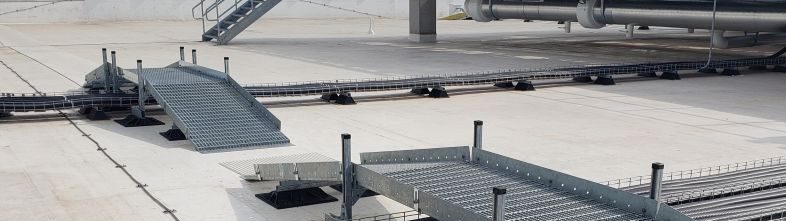
A rooftop cable tray support is a stand that holds the cable tray above the roof surface. In commercial rooftop applications, these supports are most often non-penetrating: rather than fastening through the membrane, they rest on weight-distributing bases. Most are built from adjustable steel struts mounted on those bases, where the struts carry and level the tray, and the bases spread the load across the roof so it is not concentrated at a single point.
A well-designed support does three things: it elevates the tray for drainage, airflow, and inspection access; it protects the membrane by distributing weight rather than puncturing it; and it is built to stay stable through wind and thermal movement and to resist UV and washdown exposure. MIRO Industries builds these systems from hot-dip galvanized steel strut on UV-stable polycarbonate bases with stainless hardware, a combination chosen to hold up in the corrosive micro-climate of a working rooftop.
Single-tier vs. multi-tier: how to support stacked cable tray
The first decision is how many tiers the run carries.
Single-tier runs can sit on a simple strut-and-base pipestand sized to the tray width. This covers most light-to-moderate cable routing.
Multi-tier runs call for an H-frame stand: a vertical strut frame that supports two or more tiers stacked above one base footprint. H-frames keep a dense bundle of trays organized in a small rooftop area, maintain vertical separation between tiers, and let you add or adjust levels without disturbing the membrane below. They are a common choice when cable volume is high and roof space is tight, which is typical in data centers and large commercial roofs.
MIRO Industries supports rooftop cable trays with two product families that map onto this single-tier versus multi-tier split. For lower, single-tier runs, the Strut Series base supports use standard 1-5/8 inch channel strut on UV-stable polycarbonate bases, in widths from 8 to 48 inches and heights up to 18 inches off the roof, with on-site height adjustment; many models are built specifically for cable trays. For taller single-tier runs or stacked multi-tier layouts, the galvanized steel H-frame duct supports take over: the standard Mighty H-Frame line offers 16 models in 18- to 48-inch widths with bases rated for 600 to 1,000 pounds of uniform load, and the custom 6-DS, 8-DS, and 10-DS supports add multi-tier, enclosed, and seismic or wind-rated configurations for heavier loads. See MIRO Industries’ strut supports and rooftop duct supports for both lineups.
How non-penetrating cable tray supports protect the roof
Penetrating stands fasten through the roof, creating exactly the holes a membrane is designed not to have. Each penetration is a potential leak path, and unless it is detailed, flashed, and approved under the roofing manufacturer’s requirements, it can jeopardize warranty coverage. A non-penetrating support avoids this by using a broad base that distributes the tray’s weight across the roof surface, leaving the membrane intact; some systems are self-ballasted.
This approach can also speed installation and reduce risk. With no roof coring, flashing, or cure time, the work can come off the critical path, and keeping the membrane sealed helps reduce the leak-related callbacks and warranty claims that penetrations may cause. Properly designed non-penetrating supports can also accommodate normal roof movement and thermal expansion while distributing load across the membrane.
Maintaining separation, bend radius, and code clearances
Cable tray rarely runs alone on a roof. It shares space with conduit, pipe, and mechanical lines, and the support layout has to keep those systems properly organized. Good practice is to plan tray and pipe supports together so the layout preserves access, respects each cable’s minimum bend radius as specified by the cable manufacturer, and maintains the installation and working-space clearances required by applicable codes, such as NEC Article 392 for cable tray systems and the working-space requirements of NEC Article 110.
Specifying matched tray and pipe supports from one source makes this easier: a single layout covers trays, stands, and pipe supports together, which simplifies submittals and keeps separation and clearance consistent across the whole roof. Support spacing, loading, and installation should follow the cable tray and support manufacturer’s requirements and applicable standards such as NEMA VE 2 and NEC Article 392.
How to specify rooftop cable tray supports in five steps
- Map the run. Trace each tray route across the roof and note widths, turns, and where it shares space with pipe or conduit.
- Count the tiers. Decide between single-tier stands and multi-tier H-frames based on how many tray levels each run carries.
- Calculate the load. Add the filled weight of the cable so each support and base is sized for the actual load. Strut-based systems are typically rated as an allowable uniform load per foot, so confirm the rating method and capacity for the specific support.
- Set height and clearances. Choose the clearance above the roof, and confirm separation, bend radius, and required working-space clearances relative to nearby lines and equipment.
- Set spacing. Use the cable tray manufacturer’s published span ratings and loading tables, as referenced by NEC Article 392, rather than a fixed rule, since spacing drives both sag and the load on each base.
Why cable tray supports matter on data center rooftops
Data center roofs concentrate a lot of cable in a small area under a tight schedule, which is where non-penetrating cable tray supports earn their place. Prefabricated, non-penetrating H-frame stands typically install faster than penetrated supports because they generally avoid roof coring and flashing work, they protect a membrane that cannot afford a leak over critical infrastructure, and they can be sourced alongside walkways, equipment stands, and pipe supports on a single order. See MIRO Industries’ rooftop data center solutions for how tray supports fit into a full rooftop system and the rooftop support blocks guide for supporting the smaller conduit and pipe that run alongside.
Routing cable tray on a roof or data center project? MIRO Industries builds non-penetrating cable tray supports and multi-tier H-frame stands, alongside matched pipe, conduit, and access systems, as a single source. Request a quote or find your MIRO rep.