Meeting ASCE 7-22 seismic and wind load requirements on a commercial rooftop does not require penetrating the roof membrane. Non-penetrating rooftop pipe supports, designed with wide base footprints and engineered ballast or cable bracing systems, can satisfy both the structural demands of ASCE 7-22 and the installation requirements of membrane manufacturers, helping preserve roof warranty coverage.
For engineers and facility managers, rooftop installations present a persistent challenge: building codes require that equipment be secured against seismic and wind forces, yet roofing manufacturers strictly govern penetrations to protect the building envelope. This guide explains how to navigate that intersection, covering applicable standards, load distribution, material selection, documentation, and the most common compliance questions.
1. Understanding ASCE 7 Seismic and Wind Load Requirements for Rooftop Supports
The governing standard for rooftop structural loads in the United States is ASCE 7-22 (“Minimum Design Loads and Associated Criteria for Buildings and Other Structures”), published by the American Society of Civil Engineers. ASCE 7-22 establishes minimum design loads and associated criteria for non-structural components, including rooftop piping, ductwork, and HVAC equipment, covering both seismic and wind forces.
Source: ASCE 7-22, “Minimum Design Loads and Associated Criteria for Buildings and Other Structures.” American Society of Civil Engineers. asce.org. Adopted by reference in IBC 2021 and most U.S. model building codes.
Seismic Design Categories (SDC)
ASCE 7-22 Chapter 11 assigns every project a Seismic Design Category (SDC) from A through F based on geographic location, soil conditions, and occupancy (Risk Category). The SDC determines which seismic design requirements apply to a structure and its non-structural components. The SDC for a given site can be determined using the USGS Seismic Design Maps tool (earthquake.usgs.gov/designmaps).
Non-structural components such as rooftop pipe supports are governed by ASCE 7-22 Chapter 13. Whether a given support requires seismic design depends on the project’s SDC, the component’s weight, and its assigned Importance Factor (Ip), as defined in Table 13.2-1. Some lighter, lower-importance components may qualify for exemptions even in higher SDCs. The project’s structural engineer of record is responsible for determining which requirements apply and whether any exemptions are relevant.
Source: ASCE 7-22, Sections 11.6 (Seismic Design Category) and Chapter 13 (Seismic Design Requirements for Nonstructural Components).
Wind Load Requirements
ASCE 7-22 Chapter 26 establishes the design wind speed and exposure category for a given site. Chapter 29 addresses wind loads on rooftop structures and equipment, including building appurtenances. In high-wind zones, particularly coastal regions, rooftop supports must be engineered to resist uplift forces without moving across the membrane surface. Support movement can abrade the membrane surface over time, potentially leading to premature wear.
Source: ASCE 7-22, Chapter 26 (Wind Loads — General Requirements) and Chapter 29 (Wind Loads on Building Appurtenances and Other Structures).
2. The Non-Penetrating Advantage: Seismic and Wind Compliance Without Compromising the Warranty
Traditional methods of securing rooftop supports involved bolting systems directly into the structural deck. While mechanically effective, every roof penetration introduces additional leak risk and may affect warranty coverage unless installed in accordance with the membrane manufacturer’s approved details and procedures. Non-penetrating supports can significantly reduce those concerns when properly engineered and installed.
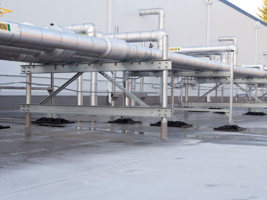
Non-penetrating rooftop supports, such as the wind and seismic pipe support systems from MIRO Industries, use engineered bases that sit on the membrane surface without fastening through it. These systems satisfy wind and seismic requirements through two primary mechanisms:
- Weighted ballast: Additional weight added to the support base counteracts wind uplift forces. The required ballast is calculated based on the site’s design wind speed (ASCE 7-22 Chapter 26) and the support’s base geometry.
- Cable bracing and stanchions: Non-penetrating tether and stanchion systems secure equipment laterally to the building perimeter or structural members rather than fastening through the deck. MIRO Industries’ engineering team provides project-specific stanchion and bracing designs as part of the Wind & Seismic product line.
3. Calculating Load Distribution and PSI Limits on the Roof Membrane
A common cause of membrane warranty complications is excessive point loading, when a support system concentrates too much load over too small a footprint, depressing the insulation beneath and creating a bowl where water pools.
When selecting rooftop pipe supports or roof duct supports, it is critical to verify the pounds per square inch (PSI) the support base exerts on the membrane:
Load (lbs) ÷ Base footprint area (in²) = PSI on membrane surface
There is no single universal PSI limit; the threshold varies by membrane manufacturer, insulation type, and assembly configuration. Always consult your specific membrane manufacturer’s published load limits and have the project engineer verify load distribution calculations for your support selection.
MIRO Industries’ rooftop supports are designed with wide base footprints to distribute pipe and equipment loads across a larger membrane contact area.
4. Material Durability for Seismic and Wind Applications: Corrosion-Resistant Steel
Seismic and wind compliance is not only a matter of design but also of longevity. A support that corrodes and fails transfers its load unevenly to the membrane and can shift during a seismic or wind event, causing membrane damage or equipment dislocation.
For exposed rooftop environments, MIRO Industries specifies the following metallic components in its supports:
G90 Galvanized Steel
The G90 designation, as defined by ASTM A653/A653M, specifies a zinc coating weight of 0.90 oz/ft² total (both sides combined), or approximately 0.45 oz/ft² per side. G90 is a continuous hot-dip process coating that provides greater corrosion resistance than lighter G60-grade alternatives.
G90 continuous-process galvanizing is commonly used in commercial rooftop support applications and provides suitable corrosion resistance in many standard environments. However, more aggressive coastal, industrial, or chemically exposed environments may warrant heavier coatings such as batch hot-dip galvanizing per ASTM A123, or stainless steel components. The right specification depends on environmental severity, expected service life, maintenance access, and exposure to coating damage. Consult your engineer or a corrosion specialist when in doubt.
Sources: ASTM A653/A653M “Standard Specification for Steel Sheet, Zinc-Coated (Galvanized) or Zinc-Iron Alloy-Coated (Galvannealed) by the Hot-Dip Process” (defines G90 coating class). American Galvanizers Association (galvanizeit.org) for environment-specific coating guidance.
Stainless Steel (Type 304)
Used in MIRO Industries’ Roller Pipe Supports. Type 304 stainless steel provides superior corrosion resistance for applications near coastal areas or industrial environments with elevated chemical exposure.
Custom-Engineered Solutions
For extreme environments, MIRO Industries offers project-specific engineering, including configurations designed to meet specific seismic and wind load calculations.
5. Documentation for Warranty and Code Compliance
For a rooftop warranty to remain enforceable during a claim, building owners and facility managers must maintain a documented record of compliance. Three categories of documentation are essential:
Stamped Engineering Drawings
Before installation, obtain stamped shop drawings from a licensed professional engineer confirming that the support layout meets the applicable seismic and wind codes for the project’s jurisdiction.
Manufacturer Installation Guidelines
Follow MIRO Industries’ published installation guidance available through the Specifier Resources page. Deviations from published installation procedures can give a membrane manufacturer grounds to deny a warranty claim independent of product performance.
Semi-annual Inspection Records
The National Roofing Contractors Association (NRCA) recommends that building owners schedule professional roof inspections at least twice per year, typically in spring and fall, as well as after severe weather events. Inspection records should document observed roof conditions, including the condition and positioning of rooftop supports and any membrane contact points, to help identify movement or damage over time.
Source: National Roofing Contractors Association (NRCA). “NRCA recommends all building owners and homeowners schedule roof system inspections at least twice per year in the spring and fall.” — nrca.net.
Summary Compliance Checklist
| Step | Action | Reference |
| 1 | Identify your Seismic Design Category (SDC) | ASCE 7-22, Ch. 11; USGS Seismic Design Maps (earthquake.usgs.gov/designmaps); structural engineer to confirm applicability per Table 13.2-1 |
| 2 | Determine wind exposure category and design wind speed for your site | ASCE 7-22, Ch. 26 |
| 3 | Select non-penetrating rooftop supports; for penetrating supports, follow membrane manufacturer’s approved details | Membrane manufacturer guidelines |
| 4 | Verify PSI exerted on roof membrane; consult membrane manufacturer’s published load limits | Membrane manufacturer spec sheets |
| 5 | Specify corrosion-resistant steel matched to your environment (G90 for standard conditions; heavier coatings or stainless for aggressive environments) | ASTM A653 (G90); ASTM A123 (batch hot-dip); MIRO product pages |
| 6 | Obtain P.E.-stamped shop drawings for wind/seismic compliance | Local AHJ requirements |
| 7 | Maintain a semiannual inspection log per NRCA recommendations | NRCA (nrca.net) |
Design a Code-Compliant, Warranty-Safe Rooftop Support System
MIRO Industries offers a complete line of rooftop pipe supports, duct supports, and wind and seismic engineered support systems, all backed by a 20-year warranty and made in the U.S.A. For projects requiring seismic or wind load compliance, MIRO Industries’ engineering team can provide stamped drawings and calculation packages.
Send us a message or request a quote to discuss your project requirements.
| Disclaimer: This article is provided for general informational purposes only and does not replace project-specific engineering analysis, manufacturer requirements, or local code review. Always consult a licensed professional engineer and the applicable Authority Having Jurisdiction (AHJ) before finalizing any rooftop support design. |
Related Reading:
- Roof Pipe Support with Roller Technology: How to Choose the Right Pipe Roller Support
- Best Practices for Securing Pipes on Commercial Rooftops
- Costly Mistakes to Avoid When Installing Rooftop Pipe Supports
- How to Choose the Right Rooftop Mechanical Unit Support
- MIRO Industries Take-Off Services Process